Introduction: The “Input Error” That Costs Thousands
Let’s be honest: modern FEA software (like Ansys or SolidWorks) makes us lazy. You pick a material, hit “Run,” and look at the colorful stress map.
But there is a hidden trap. When you select “Nylon” or “Aluminum” from the library, the software usually gives you just one number for stiffness: Young’s Modulus.
If you are pulling a bar, that’s fine. But what if you are twisting a shaft? Or bending a plastic clip? Or sealing a deep-sea camera?
Using “Young’s Modulus” for everything is like using a hammer for every screw. It doesn’t work.
- Twisting requires Shear Modulus.
- Squeezing requires Bulk Modulus.
- Bending Plastic requires Flexural Modulus.
This guide explains these 4 types of stiffness in plain English—no PhD required—so you can choose the right one and stop your parts from failing.
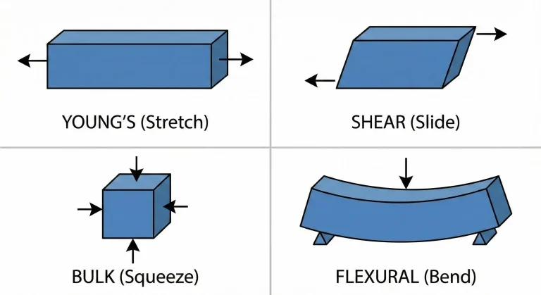
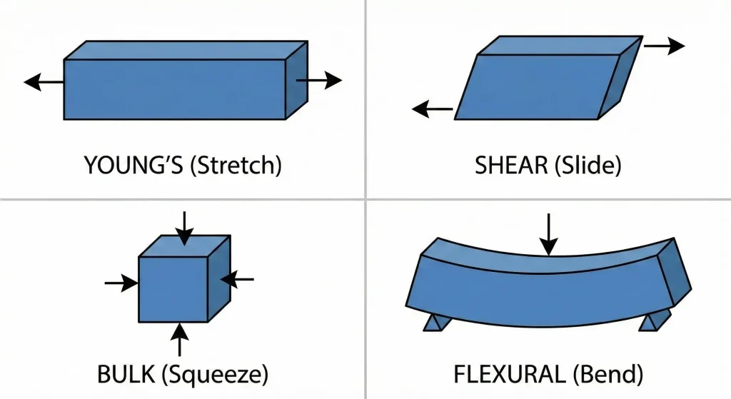
1. Young’s Modulus (E): The “Stretch” Stiffness
Also known as: Tensile Modulus.
This is the celebrity of the group. It answers one simple question: “How much does it stretch when I pull it?”
The “Spring” Analogy
Imagine atoms are connected by tiny springs.
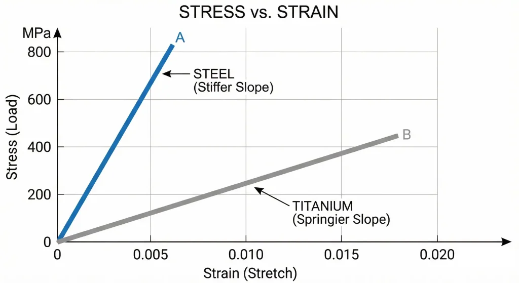
- Steel: The springs are incredibly stiff. You pull, it barely moves. ($E \approx 200$ GPa).
- Plastic: The springs are loose and floppy. You pull, it stretches easily. ($E \approx 2$ GPa).
The “Titanium vs. Steel” Myth
Junior engineers often think Titanium is “stiffer” than Steel because it’s used in fighter jets.Wrong. Titanium is stronger for its weight, but it is actually bouncier.
- Steel: Stiff like a rock.
- Titanium: Springy (about 50% as stiff as steel).
If you build a bicycle frame out of Titanium with the exact same tube thickness as Steel, the Titanium bike will feel “noodly” and flex twice as much.
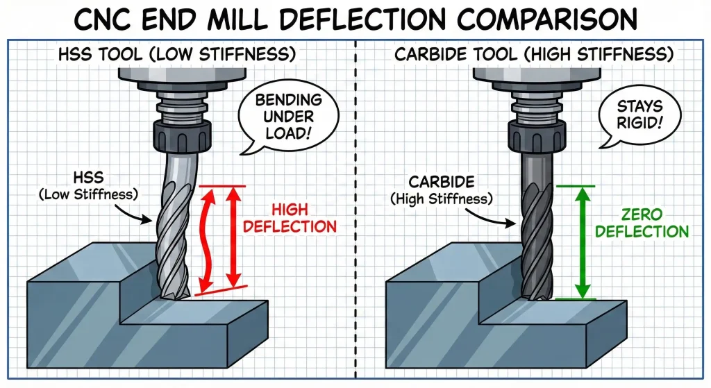
Why CNC Machinists Care (Tool Deflection)
We use Young’s Modulus to calculate how much a cutter bends.The Formula:
Deflection = (Force × Length³) / (3 × E × Inertia)
See that Length³? It means if the tool sticks out 2x longer, it bends 8x more! See the E? Since Carbide ($E=600$) is 3x stiffer than Steel ($E=200$), we use Carbide tools to stop the bending.
2. Shear Modulus (G): The “Twist” Stiffness
Also known as: Modulus of Rigidity.
Young’s Modulus is for pulling. Shear Modulus is for sliding and twisting.
The “Deck of Cards” Analogy
Imagine a deck of cards sitting on a table.
- Compression (Young’s): You push down on the top card. The deck gets thinner.
- Shear (G): You slide the top card sideways. The whole deck tilts into a parallelogram shape. That is Shear.
The Drive Shaft Trap
If you are designing a motor shaft or a leadscrew, the main force isn’t pulling—it’s Twisting (Torque). The resistance to twisting depends on G, not E.
The Twist Formula:
Angle of Twist = (Torque × Length) / (Polar Inertia × G)
The Trap: For most metals, Shear Modulus ($G$) is only about 38% of Young’s Modulus ($E$). If you mistakenly use Young’s Modulus in your calculation, you will think your shaft is super stiff. In reality, it will twist 2.5x more than you predicted, leading to vibration or failure.
3. Bulk Modulus (K): The “Squeeze” Stiffness
Also known as: Volumetric Modulus.
This answers the question: “How much does it shrink if I squeeze it from all sides?”
The “Submarine” Analogy
Imagine throwing a ball into the deepest part of the ocean. The water pressure pushes on it from every direction.
- High Bulk Modulus: The ball keeps its size (like Steel).
- Low Bulk Modulus: The ball shrinks into a raisin (like Foam).
Is Water Compressible?
We usually say “liquids don’t compress.” That’s a lie. At the extreme pressures of a Waterjet Cutter (60,000 PSI), water actually compresses! If you are designing high-pressure hydraulic seals or deep-sea ROVs, you must check the Bulk Modulus ($K$), or your seals might leak as the material shrinks under pressure.
4. Flexural Modulus (E-flex): The “Plastic” Trap
Also known as: Bending Modulus.
This is where 90% of design errors happen. Ideally, “Stiffness in Bending” should be the same as “Stiffness in Pulling.” For metals, this is true. For Plastics, it is NOT.
The “Bread Crust” Analogy (Skin Effect)
Injection molded plastic is like a loaf of bread.
- The Skin (Crust): The plastic touches the cold mold wall and freezes instantly. The molecules align perfectly. This layer is hard and stiff.
- The Core (Inside): The inside cools slowly and stays messy (amorphous). This part is soft.
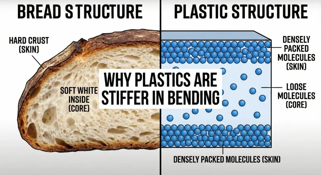
When you bend a plastic beam, the stress is mostly on the Skin (the stiffest part). Therefore, plastics often resist bending more than they resist pulling.
The Rule: If you are designing a Snap-Fit or a Clip:
- Ignore the Tensile Modulus (ASTM D638).
- Use the Flexural Modulus (ASTM D790). If you don’t, your snap-fit might be too stiff to assemble, or it might snap off.
5. The Cheat Sheet: How they relate
You don’t always need to test for everything. For metals (like Steel and Aluminum), these numbers are mathematically linked by Poisson’s Ratio (v)—which is just a fancy way of saying “how much it gets thinner when stretched.”
The Magic Formulas (Simplified):
- To find Shear Modulus (G):G ≈ E ÷ 2.6(Roughly 38% of Young’s Modulus)
- To find Bulk Modulus (K):K = E ÷ [3 × (1 – 2v)]
- Key Takeaway: If you know the Young’s Modulus ($E$) and the Poisson’s Ratio ($v$), you can calculate the others. But for Plastics? Don’t calculate. Check the datasheet.
Conclusion: Choose the Right Number
Engineering is about precision.
- Designing a Tie Rod? Focus on Young’s ($E$).
- Designing a Drive Shaft? Focus on Shear ($G$).
- Designing a Submarine? Focus on Bulk ($K$).
- Designing a Plastic Clip? Focus on Flexural ($E_{flex}$).
At JFManufacturer, we don’t just blindly follow the drawing. We review the physics of your design. If we see a material choice that looks risky for the application, we will flag it before we cut a single chip.
Need a second opinion on your design? Upload your CAD file for a free DFM review.
FAQ
Stiffness (Modulus) is how much a material “springs back” when you bend it. Hardness is how hard it is to scratch or dent the surface. A rubber wheel is Hard (abrasive) but not Stiff. A gold ring is Stiff but not Hard (easy to scratch).
At an atomic level, it is generally easier to slide atoms past each other (Shear) than to pull them completely apart (Tension). For most metals, Shear stiffness is only about 40% of Tensile stiffness.
No, you should not calculate it from Young’s Modulus. Because plastics have a “skin-core” structure from injection molding, they behave differently in bending vs. tension. Always look for “ASTM D790” on the material datasheet.