In the world of precision manufacturing, “exact” is a theoretical concept, not a reality. No machine—no matter how advanced—can produce a part that is perfectly 100.000 mm long every single time. There will always be a microscopic degree of variation.
CNC Machining Tolerances are the boundaries we set to define how much variation is acceptable before a part is considered “failed.”
For engineers and product designers, understanding tolerances is not just about ensuring parts fit together; it is the single most effective lever for controlling project costs. Over-tolerancing (asking for tighter precision than necessary) can triple your manufacturing costs, while under-tolerancing can lead to catastrophic assembly failures.
This comprehensive guide covers everything you need to know about CNC tolerances, from international standards (ISO 2768) to Geometric Dimensioning and Tolerancing (GD&T), helping you design better parts for less money.
1. What is a Machining Tolerance?
In CNC machining, a tolerance is the allowable limit of variation in a physical dimension. It is typically expressed as a range (±). It tells the machinist: “This part needs to be 10mm, but if it’s between 9.95mm and 10.05mm, it’s still acceptable.”
If you do not specify a tolerance on a specific dimension, manufacturers will apply their “Standard” or “General” tolerance (typically ±0.1mm or ISO 2768-m).
2. Types of Tolerances
Understanding how to annotate tolerances on your 2D drawings is crucial for communicating your intent.
Bilateral Tolerances
Variation is allowed in both directions from the nominal dimension. This is the most common type.
- Example: 20 mm ± 0.05 mm.
- Meaning: The part can be anywhere between 19.95 mm and 20.05 mm.
Unilateral Tolerances
Variation is allowed in only one direction. This is critical for mating parts where a component can be smaller but never larger than the hole it fits into.
- Example: 20 mm +0.00 / -0.10 mm.
- Meaning: The part can be 19.90 mm to 20.00 mm, but never 20.01 mm.
Limit Tolerances
Instead of a nominal size and a deviation, you simply state the upper and lower limits.
- Example: 19.95 – 20.05 mm.
3. General Tolerances: The ISO 2768 Standard
You don’t need to specify a tolerance for every single dimension on your drawing. That would make the drawing unreadable. For non-critical dimensions, the industry relies on General Tolerances.
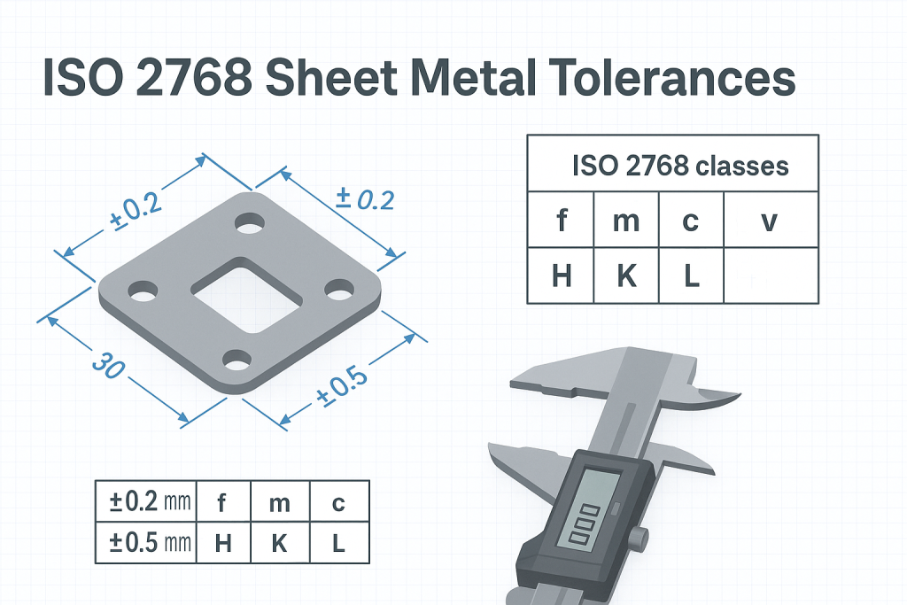
The most widely accepted standard in Europe and Asia (and globally for metric parts) is ISO 2768.
ISO 2768 is divided into four tolerance classes:
- f (fine)
- m (medium) – The Industry Standard for Metal CNC Parts
- c (coarse)
- v (very coarse)
Unless you specify otherwise, JFManufacturer applies ISO 2768-m to all machined parts.
ISO 2768-m (Medium) Linear Dimensions Table
| Nominal Length Range (mm) | Tolerance (mm) |
| 0.5 up to 3 | ±0.1 |
| Over 3 up to 6 | ±0.1 |
| Over 6 up to 30 | ±0.2 |
| Over 30 up to 120 | ±0.3 |
| Over 120 up to 400 | ±0.5 |
| Over 400 up to 1000 | ±0.8 |
4. Advanced Precision: Introduction to GD&T
Traditional linear tolerances (like ±0.1mm) control size and position, but they don’t control shape.
Imagine a flat plate. You can specify its thickness is 10mm ±0.1mm. However, the plate could be warped like a potato chip and still meet that thickness requirement at every measured point. To prevent this, we use Geometric Dimensioning and Tolerancing (GD&T).
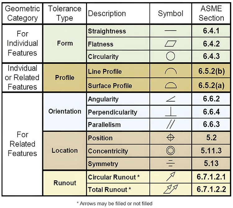
GD&T uses symbols to control specific geometric characteristics. Here are the most common ones you should know:
- Flatness (⏥): Ensures a surface is perfectly flat within a specified zone. Crucial for sealing surfaces.
- Concentricity (◎): Ensures two cylinders (like a pipe wall) share the exact same center axis.
- Perpendicularity (⊥): Ensures a surface is exactly 90 degrees to a reference datum.
- True Position (⌖): The most powerful symbol. It defines the exact center of a hole relative to datums, often allowing for “bonus tolerance.”
5. Engineering Fits: Clearance, Transition, and Interference
When two parts need to mate (e.g., a shaft inserting into a bearing), specifying a simple tolerance isn’t enough. You need to design for a specific “Fit.” We generally follow ISO 286 for these calculations.
A. Clearance Fit (The “Slide” Fit)
The shaft is always smaller than the hole. There is always a gap.
- Use case: A pin that needs to slide in and out of a hole easily. Door hinges.
- Typical Tolerance: H7/g6
B. Transition Fit (The “Snug” Fit)
The tolerances overlap. The shaft can be slightly larger or smaller than the hole. It might require light force (like a rubber mallet) to assemble.
- Use case: Alignment pins, parts that need to be disassembled occasionally for maintenance.
- Typical Tolerance: H7/k6
C. Interference Fit (The “Press” Fit)
The shaft is always larger than the hole. The parts must be forced together using a hydraulic press or by shrinking the shaft with liquid nitrogen. They are held in place by friction.
- Use case: Bearings mounted in housings, dowel pins that must never move.
- Typical Tolerance: H7/p6
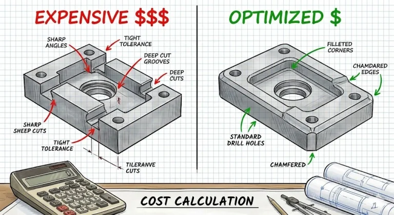
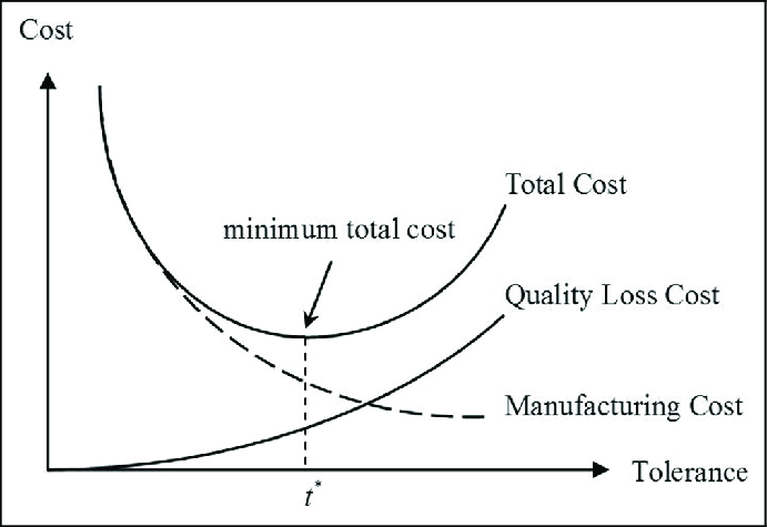
6. The Cost of Precision: Finding the Sweet Spot
This is the most critical section for your budget. Cost does not rise linearly with precision; it rises exponentially.
Asking for ±0.01mm instead of ±0.05mm might double your part cost. Why?
- Slower Machining: The machine must run slower to minimize vibration.
- Specialized Tooling: We may need to use brand-new end mills for your finish passes.
- Temperature Control: Thermal expansion becomes an issue.
- Scrap Rate: The risk of rejecting a part increases.
The Golden Rule for Designers:
Only apply tight tolerances (±0.01mm) to critical mating features (holes, shafts, alignment surfaces). For everything else (external walls, non-mating pockets), open up the tolerance to standard ISO 2768-m (±0.1mm – ±0.2mm).
7. How to Inspect Tolerances
How do we ensure we hit these numbers? At JFManufacturer, we employ a tiered inspection process.
- Calipers & Micrometers: For standard linear tolerances (±0.1mm).
- Go/No-Go Gauges: For quickly checking holes and threads on the production line.
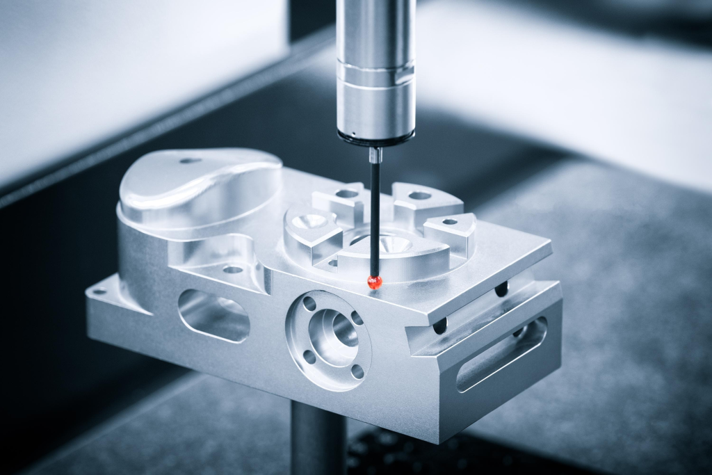
- CMM (Coordinate Measuring Machine): For GD&T and tight tolerances (< ±0.02mm). The CMM uses a ruby-tipped probe to map the part’s geometry in 3D space.

8. JFManufacturer’s Standard Tolerance Capabilities
We pride ourselves on delivering precision you can trust.
- Standard Metals: ±0.1mm (ISO 2768-m)
- Standard Plastics: ±0.2mm (Due to stress and thermal expansion)
- Precision CNC Machining: Down to ±0.01mm (0.0004″) upon request.
- Precision Grinding: Down to ±0.005mm (0.0002″).
Need help defining the tolerances for your project?
Don’t let over-tolerancing kill your budget. Upload your CAD file and 2D drawings to JFManufacturer. Our engineers will review your GD&T and linear dimensions, providing DFM feedback to optimize both performance and cost.