“Why does this bracket cost $150?”
It is the most common question in manufacturing. The answer is rarely “corporate greed.” The answer usually lies hidden in a corner radius that is too small, a tolerance that is unnecessarily tight, or a feature that forces a machine operator to manually flip the part three times.
CNC machining is a subtractive process. It is inherently expensive because you are paying for three things:
- Material Removal: Turning a solid block into chips.
- Machine Time: High-end 5-axis mills cost $150+ per hour to run.
- Risk: Tight tolerances increase the risk of scrap.
However, the price of a machined part is not fixed. In fact, up to 70% of the manufacturing cost is locked in during the design phase.
This guide is not a list of generic tips. It is a comprehensive Design for Manufacturability (DFM) handbook. We will break down the mathematics of machining costs and provide actionable engineering strategies to reduce your unit price by 30% to 50% without compromising functionality.
Part 1: The Economics of Machining (The Pricing Formula)
To lower the cost, you must understand the algorithm. Most machine shops quote based on a variation of this formula:
Cost = (Material Cost) + (Machine Rate × Cycle Time) + (Setup Time) + (Overhead/Risk)
1. The “Material Removal Rate” (MRR)
Time is money. The faster we can remove material, the cheaper the part.
- Aluminum 6061: Cuts like butter. High MRR. Low cost.
- Stainless 304: Work hardens. Requires slower speeds. Higher cost.
- Titanium: Requires slow, high-pressure cutting. Highest cost.Takeaway: Don’t specify Stainless Steel if Aluminum (with a protective coating) will suffice.
2. The Setup Penalty
Every time we have to stop the machine, open the door, unclamp the part, flip it, and re-clamp it, you are paying for Non-Cutting Time.
- A part that can be machined in one setup (e.g., on a 3-axis mill with a vise) is always cheaper than a part requiring four setups (machining all sides).
Part 2: Geometry & Features (Where Money is Lost)
The geometry of your part dictates the tool we must use. And tool limitations dictate the speed.
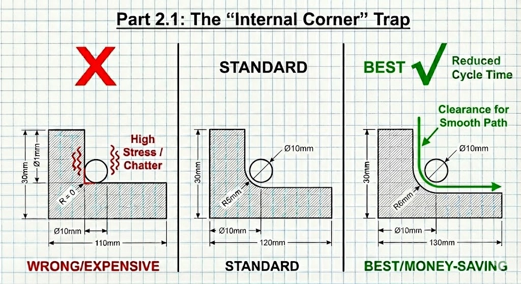
2.1 The “Internal Corner” Trap
This is the #1 cause of unnecessary cost.
CNC tools are round and rotate. They cannot cut a perfect square internal corner.
- The Problem: If you design a pocket with a vertical wall and a sharp 90° internal corner, we have to use a microscopic end mill to pick out that corner (EDM might even be required).
- The Physics: When an end mill enters a corner, the tool engagement angle spikes, causing vibration (chatter). To prevent tool breakage, the machine must slow down to a crawl.
- The Fix:
- Rule of Thumb: Make the corner radius (R) at least 1/3 of the pocket depth.
- The “Slightly Larger” Trick: If you use a standard Ø10mm tool (R=5mm), don’t design the corner radius as exactly 5mm. Design it as 5.5mm. This allows the tool to run a continuous circular path without stopping in the corner, reducing cycle time.
2.2 Deep Pockets & Thin Walls
- Deep Pockets: Long tools vibrate. To machine a pocket that is 50mm deep, we need a tool that sticks out 50mm+. If that tool is thin, we have to run it at 10% speed to stop it from snapping.
- DFM Rule: Keep the Length-to-Diameter (L:D) ratio under 4:1.
- Thin Walls: Metal is flexible. If you design a wall thickness of 0.5mm on a metal part, the force of the cutter will bend the wall, creating a tapered surface. We have to take microscopic “finish passes” to avoid this.
- DFM Rule: Keep metal walls > 0.8mm and plastic walls > 1.5mm.
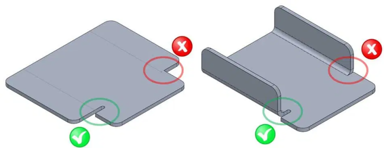
2.3 Undercuts (The Hidden Cost)
An undercut is a feature that a standard cutting tool cannot reach from above (like a T-slot or a dovetail).
- The Cost: Undercuts require specialized “lollipop” cutters or T-slot cutters. These tools are expensive, fragile, and slow. Often, they require a completely new manual setup to orient the part sideways.
- The Fix: Design undercuts only when absolutely necessary. Can the part be split into two bolted pieces to avoid the undercut?
Part 3: Tolerancing Strategy (GD&T)
“Over-tolerancing” is the silent budget killer. Engineers often apply a default tolerance block (e.g., ±0.05mm) to the entire drawing.
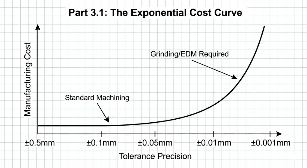
3.1 The Exponential Cost Curve
- Standard Tolerance (±0.125mm / ±0.005″): Standard machining speed. Cost: 1x.
- Precision Tolerance (±0.025mm / ±0.001″): Requires a finishing pass and slower feeds. Cost: 2x.
- High Precision (±0.005mm / ±0.0002″): Requires grinding or honing and temperature control. Cost: 5-10x.
3.2 Define “Critical” vs. “Reference”
Does the aesthetic chamfer on the outside of the casing really need to be ±0.01mm? No.
- DFM Strategy: Use Geometric Dimensioning and Tolerancing (GD&T) to be specific.
- Apply tight tolerances (e.g., H7 hole fit) ONLY to mating surfaces (bearing bores, dowel holes).
- Leave all other dimensions as “Reference” or “Open Tolerance” (ISO 2768-m).
Part 4: Material Selection & Stock Sizes
Designers often forget that raw material comes in standard bars and sheets.
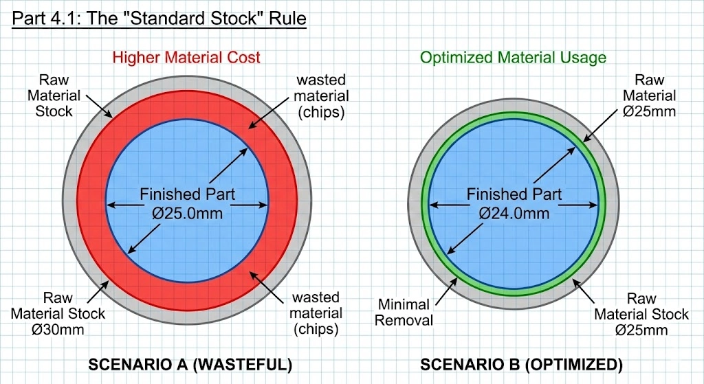
4.1 The “Standard Stock” Rule
If you design a part with a final outer diameter of 25.0mm, we cannot use a 25mm bar because we need to machine the outer surface to make it true. We have to buy the next size up: 30mm (or 1.25 inch).
- The Waste: We then have to turn that 30mm bar down to 25mm, turning 20% of the material into useless chips.
- The Fix: Design the part to be 24.0mm or 22.0mm if possible. This allows us to use the 25mm stock, reducing material waste and machining time.
4.2 Machinability Ratings
Not all metals cut the same.
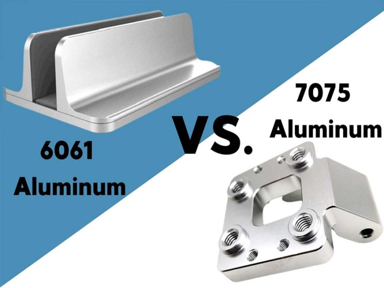
- Aluminum 6061: Machinability 100% (Baseline).
- Aluminum 7075: Machinability 80% (More expensive, harder).
- Steel 1018: Machinability 78%.
- Stainless 304: Machinability 45% (Costs significantly more in run-time).
- Titanium Gr5: Machinability 15% (Costs 4-6x more than Aluminum).
Action: If your part doesn’t need the corrosion resistance of 304 Stainless, switch to 12L14 Steel (leaded steel) or Aluminum 6061 with nickel plating.
Part 5: Design for Fixturing (Workholding)
How do we hold your part? If the shape is weird/organic, we can’t use a standard vise. We have to machine a custom fixture (Soft Jaws), which you pay for.
- Parallel Surfaces: Try to design at least two parallel surfaces so we can clamp it in a standard vise.
- The “Tab” Method: For small or complex parts, allowing us to leave “tabs” (small connections to the raw stock) can simplify machining. We break the tabs off and sand them down later.
5.1 3-Axis vs. 5-Axis: Counter-Intuitive Economics
You might think 5-axis machining is always more expensive. Not always.
- Scenario: A complex housing needs holes drilled on 5 different sides.
- 3-Axis Method: Operator loads part → Machines Side A → Stops → Flips part → Machines Side B… (Repeat 5 times). Result: High labor cost, cumulative tolerance errors.
- 5-Axis Method: Operator loads part once. Machine rotates to hit all 5 sides. Result: Higher hourly rate, but drastically lower labor time and higher accuracy.
- Verdict: For multi-sided parts, 5-axis is often the cost-effective choice.
Part 6: Text and Engraving
Adding part numbers or logos?
- Embossed (Raised) Text: Extremely Expensive. To make the text stick out, we have to machine away all the material around it.
- Engraved (Recessed) Text: Cheap. We just trace the letters with a tiny ball-nose cutter.
- Pro Tip: Use a sans-serif font (like Arial) and ensure the stroke width is at least 0.5mm. Even better? Use Laser Marking post-process. It’s faster, cheaper, and sharper.
Conclusion: Partner Early
Cost reduction doesn’t happen on the shop floor; it happens at the CAD station. Once the design is frozen, 90% of the cost-saving opportunities are gone.
At JFManufacturer, we don’t just quote files; we analyze them. Our automated DFM tools and experienced engineers look for the “cost drivers”—the deep pockets, the unnecessary tolerances, the awkward undercuts—and suggest alternatives.
Want to lower your BOM cost?
Upload your 3D model today for a free DFM Review. We’ll show you exactly where you can save money without sacrificing performance.
[Get Your DFM Analysis & Quote]
FAQ: CNC Cost Reduction
It depends on volume. For 1-5 prototypes of complex shapes, 3D printing (SLS/SLA) is often cheaper. For 10+ parts, or parts requiring high strength and threads, CNC machining becomes more cost-effective.
Aluminum 6061-T6 is generally the most cost-effective option. It is relatively cheap to buy and extremely fast to machine. If you need steel, 12L14 (Leaded Steel) is the cheapest to machine due to its high machinability.
Standard Type II anodizing typically adds a minimum lot charge (e.g., $80-$100) or roughly 10-15% to the unit cost for larger batches. Bulk processing is key—anodizing 100 parts is much cheaper per unit than anodizing 5.
For external edges, use Chamfers (45° bevels). A chamfer tool is standard and quick. For internal edges, you MUST use a Radius (Fillet) because the tool is round.