You have designed a perfect part. The tolerances are optimized (thanks to our [Cost Reduction Guide]), the material is selected, and the functionality is verified.
But when the box arrives and you open it, your heart sinks. The parts are scratched. The “Black” anodizing looks purple. The powder coat is so thick that the screws won’t fit into the holes.
Surface Finish is not an afterthought; it is a critical engineering specification.
In CNC machining, the “Finish” serves three purposes:
- Protection: Preventing corrosion and wear.
- Function: Reducing friction or altering conductivity.
- Aesthetics: Creating the perception of quality.
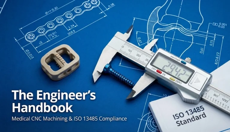
This handbook is written for mechanical engineers and industrial designers. We will move beyond the basic “Make it look nice” request and dive into the technical realities of Anodizing, Powder Coating, Passivation, and PVD. We will analyze how each process affects your part’s dimensions, tolerances, and cost.
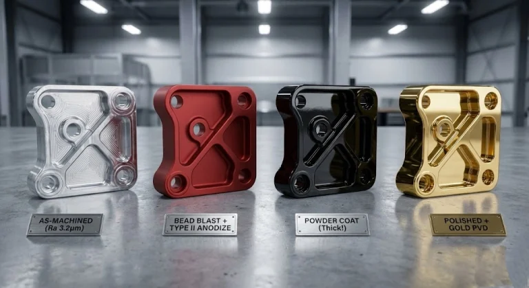
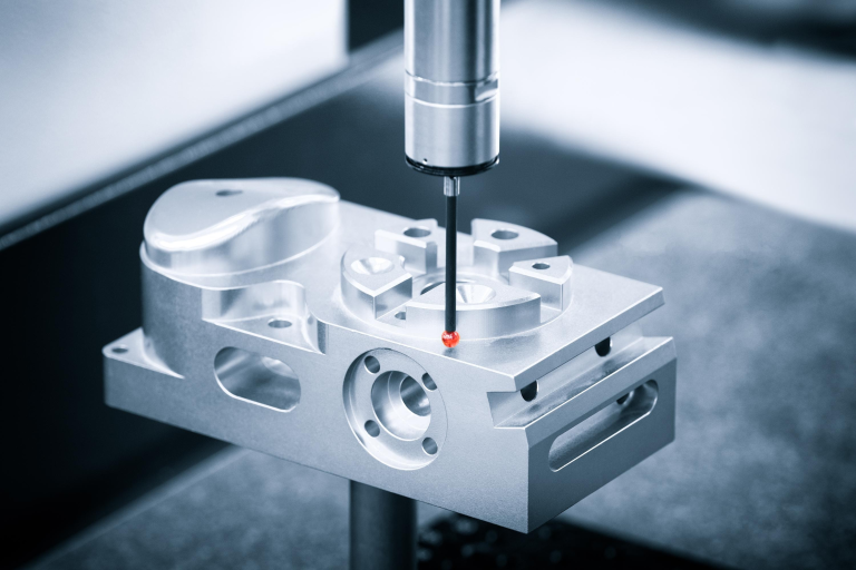
Part 1: The Baseline – “As-Machined” Standards
Before applying any coating, we must understand the canvas we are painting on.
1.1 Understanding Ra (Roughness Average)
Surface roughness is measured in Ra (Average Roughness). It measures the average deviation of the surface peaks and valleys from the mean line.
- Ra 3.2μm (125μin): The standard “As-Machined” finish. Visible tool marks (swirls) are present. It is the cheapest option because it requires no secondary passes. Ideal for internal components.
- Ra 1.6μm (63μin): A smooth finish. Tool marks are still visible but faint. Requires slower finishing passes.
- Ra 0.8μm (32μin): High-grade machine finish. Requires careful control of feeds, speeds, and tool sharpness. Visually shiny, but tool marks may still be discernible under light.
- Ra 0.4μm (16μin) and lower: Requires polishing or grinding.
1.2 Tool Marks are Not Defects
Engineers new to CNC often reject parts because they can “see lines.”
- The Reality: CNC milling is a rotary cutting process. It inherently leaves cutter paths. Unless you specify a secondary process (like bead blasting), visible tool marks are compliant with an “As-Machined” specification.
Part 2: Mechanical Finishes (Texture & Deburring)
These processes physically alter the surface by removing material or reshaping it.
2.1 Bead Blasting (The “Great Equalizer”)
Bead blasting involves shooting media (glass, sand, or ceramic) at high velocity onto the part surface.
- Purpose: It creates a uniform, matte texture (satin finish) and hides tool marks. It is the most common prep-step before anodizing.
- Media Matters:
- Glass Beads: Creates a smooth, bright satin finish. (Most common for Aluminum).
- Aluminum Oxide (Sand): Creates a darker, rougher, “etched” surface. often used as prep for painting to increase adhesion.
- The Risk: Blasting removes small amounts of material and can round over sharp edges.
- Design Note: Do not blast precision bearing bores. We must mask them, which adds cost.
2.2 Tumble Deburring (Vibratory Finishing)
Parts are placed in a vibrating tub filled with ceramic or plastic media stones.
- Purpose: To break sharp edges and create a uniform, non-directional scratch pattern.
- Pros: Very cheap (bulk processing).
- Cons: Not suitable for parts with tiny features or thin walls (they might bend).
Part 3: Electrochemical Finishes (Anodizing & Passivation)
These are chemical conversions of the metal surface. They are the most technically complex because they change the chemical composition of the “skin.”
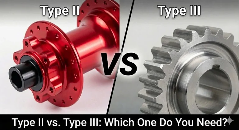
3.1 Anodizing (Type II vs. Type III) – Aluminum Only
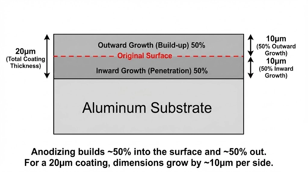
Anodizing is an electrolytic passivation process used to increase the thickness of the natural oxide layer on the surface of metal parts.
- Type II (Standard / Decorative):
- Thickness: 5μm – 25μm (0.0002″ – 0.001″).
- Function: Corrosion resistance and color. The porous oxide layer absorbs dye (Black, Blue, Red, Gold).
- Dimensional Impact: It penetrates the material and grows on top. Rough rule: 50% penetration, 50% growth. If you ask for 10μm thickness, the part grows by ~5μm per side.
- Type III (Hardcoat):
- Thickness: 25μm – 75μm (0.001″ – 0.003″).
- Function: Extreme wear resistance and electrical insulation. The surface becomes as hard as ceramic (60-70 Rockwell C).
- Color: Usually dark grey or black. It is difficult to dye bright colors due to the density of the coating.
3.2 Passivation (Stainless Steel)
Passivation does not change the appearance of the part.
- The Science: It uses Citric or Nitric acid to dissolve “free iron” from the surface, enhancing the chromium oxide layer that prevents rust.
- Dimensional Impact: Zero. It is a cleaning process.
3.3 Chem Film / Alodine (Chromate Conversion)
Used on Aluminum to provide corrosion resistance while maintaining electrical conductivity.
- Appearance: Clear (invisible) or Gold/Yellow.
- Use Case: Grounding points on electronics enclosures where anodizing (which is an insulator) cannot be used.
Part 4: Coating & Deposition (Adding Material)
These processes add a distinct layer of new material on top of the substrate.
4.1 Powder Coating
Dry powder is sprayed electrostatically and then cured under heat to form a “skin.”
- Pros: Extremely durable, scratch-resistant, hides machining defects perfectly. Cheaper than anodizing for large batches.
- Cons: Thickness! Powder coat is thick—typically 0.06mm to 0.15mm (60-150μm).
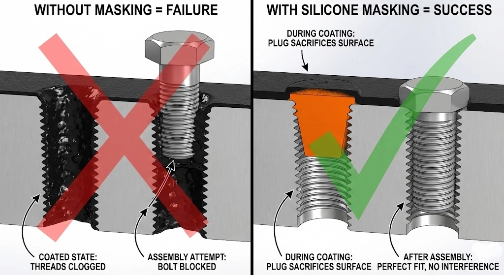
- The Engineering Trap: If you design a 10.0mm hole and powder coat it, it will shrink to 9.8mm. The screw won’t fit.
- Solution: You MUST specify “Masking Required” for threads and tight-tolerance bores.
4.2 Wet Painting
Traditional spray painting.
- Pros: Unlimited color matching (Pantone/RAL), high gloss options (automotive finish).
- Cons: Less durable than powder coat. More expensive due to labor (priming, sanding, painting, clear coating).
4.3 PVD (Physical Vapor Deposition)
The “Apple” finish. Used on high-end consumer electronics and cutting tools.
- The Process: Titanium or Zirconium is vaporized in a vacuum chamber and deposited on the part.
- Pros: Incredibly hard (diamond-like), thin (1-3μm), and beautiful metallic colors (Gold, Rose Gold, Rainbow).
- Cons: Expensive. Requires a perfectly polished surface underneath because PVD conforms to the surface—it won’t hide scratches; it highlights them.
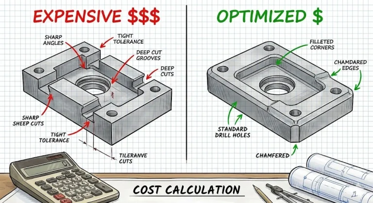
Part 5: The “Tolerance Matrix” (The Most Important Section)
This is where projects fail. As discussed in our [CNC Cost Reduction Guide] , tighter tolerances exponentially increase cost. Therefore, understanding coating thickness is critical…
| Finish Type | Typical Thickness (Growth per side) | Masking Required? | Impact on Tolerance |
| Anodizing Type II | 2 – 10 μm | No (usually) | Negligible for most parts |
| Anodizing Type III | 25 – 50 μm | YES for H7 holes | Significant. Plan for it. |
| Electropolishing | (Removes 5-10 μm) | No | Parts get smaller. |
| Powder Coating | 60 – 150 μm | CRITICAL | Massive. Mask all threads. |
| PVD | 1 – 3 μm | No | Negligible. |
| Black Oxide | < 1 μm | No | None. |
Engineering Rule: Always specify on the drawing: “Dimensions apply AFTER plating” or “Dimensions apply BEFORE plating”. If you don’t specify, the machinist has to guess.
Part 6: Defining Cosmetic Standards
“Make it look good” is not a specification. At JFManufacturer, we recommend defining Cosmetic Classes:
- Class A (Primary Visible Surface):
- No scratches visible at arm’s length (60cm).
- Uniform color and texture.
- No pits or inclusions.
- Example: The top case of a laptop.
- Class B (Secondary Visible Surface):
- Minor scratches acceptable if not felt by fingernail.
- Slight color variation allowed.
- Example: The bottom or back of a device.
- Class C (Non-Visible / Internal):
- Tool marks, scratches, and clamping marks are acceptable.
- Functionality is the only requirement.
- Example: Internal chassis brackets.
Pro Tip: Mark the “A-Side” surfaces on your PDF drawing. This tells the machinist where to place the clamps to avoid leaving marks on the pretty side.
Conclusion: The Final Touch
The surface finish is the first thing your customer sees. It is the tactile interface of your product. A brilliant mechanism hidden inside a poorly finished casing will be perceived as “cheap.”
At JFManufacturer, we don’t just dunk parts in a tank. We engineer the finish. From calculating the chemical etch rate of our anodizing tanks to designing custom silicone masks for your powder coated parts, we ensure the final micron is as precise as the first cut.
Unsure which finish fits your budget?
Upload your CAD model. Our DFM engineers will recommend the best finish for your application and highlight potential masking issues before we start cutting.
FAQ: Surface Finishes
Anodizing is a translucent crystal structure. The final color depends on the aluminum alloy (6061 vs 7075), the surface texture (blasted vs polished), and the dye. 7075 Aluminum often turns a yellowish/bronze hue when clear anodized, while 6061 remains silver.
No. Anodizing is like putting a magnifying glass on the surface. It will often make scratches more visible. If you need to hide defects, you must use Bead Blasting before anodizing.
Black Oxide is a conversion coating for Steel (mostly for corrosion resistance and low reflection). Black Anodize is for Aluminum. You cannot Black Oxide aluminum, and you cannot Anodize steel.
Yes, for hygiene. Electropolishing removes material to smooth out microscopic peaks, creating a surface that is 30x more corrosion resistant than passivation alone. It is the standard for medical and semiconductor parts.