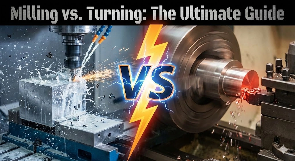
CNC Milling vs. CNC Turning: The Ultimate Comparison Guide for Engineers
Published Date:
Share
Table of Contents
Newsletter
Subscribe our newsletter to get update information, news and free insight.
In the precision manufacturing industry, the debate of CNC milling vs CNC turning often confuses beginners. While both are pillars of subtractive manufacturing, they represent fundamentally different approaches to material removal.
For product designers and engineers, understanding the distinction isn’t just about semantics—it’s about Design for Manufacturability (DFM). The choice between milling and turning dictates your part’s tolerance capabilities, surface finish, production speed, and ultimately, the unit cost.
This comprehensive guide dives deep into the mechanics, operations, and technical differences between these two processes, helping you optimize your designs for the right machine.
CNC Milling Explained: The Versatile Workhorse
CNC Milling is the most common machining process in modern manufacturing. It is defined by a specific kinematic relationship: The workpiece is stationary (clamped), and the cutting tool rotates.
The Mechanics of Milling
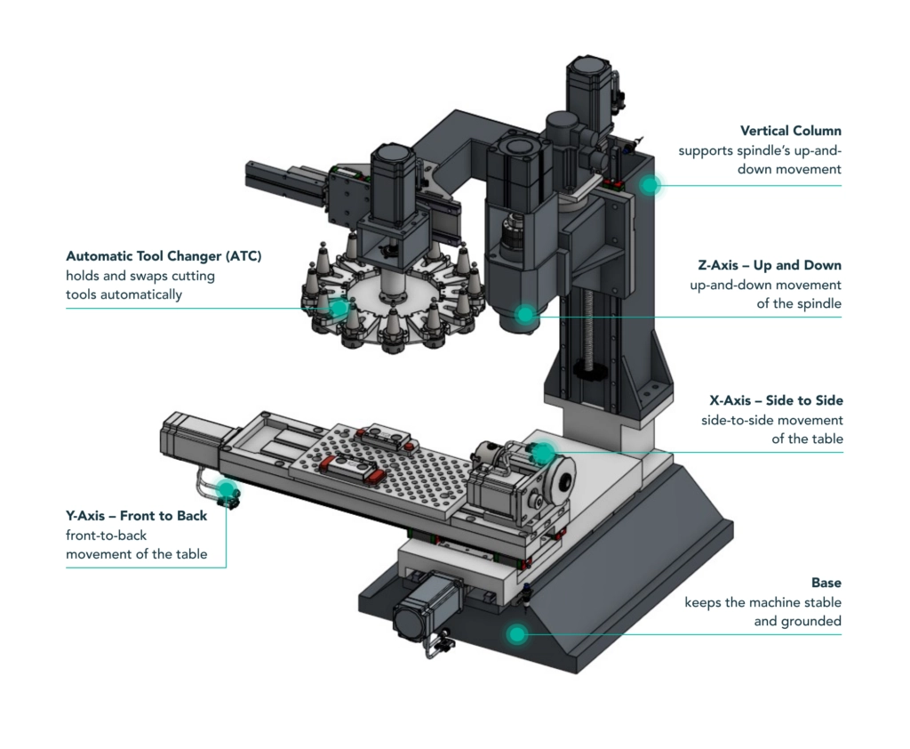
Milling machines typically operate on 3 to 5 axes. The cutting tool (spindle) rotates at high speeds (often thousands of RPM), while the table moves the workpiece into the cutter to shave material off the block.
A diagram illustrating the X, Y, and Z axes movement on a vertical CNC milling machine with a rotating spindle.
Because the cutter has multiple teeth and rotates, milling involves interrupted cutting. Each tooth engages and disengages with the material repeatedly. This allows the tool to cool down slightly between cuts but introduces mechanical shock, which can affect tool life and surface finish if not managed correctly.
Key Milling Sub-Processes
Face Milling: Uses a large diameter cutter to create perfectly flat surfaces.
Peripheral (End) Milling: Uses the side of the cutter to machine slots, pockets, and profiles.
Chamfer Milling: Creates angled edges to deburr or prepare parts for welding.
CNC Turning Explained: The Cylindrical Specialist
CNC Turning is performed on a machine called a Lathe. It is defined by the inverse relationship to milling: The workpiece rotates, and the cutting tool is stationary.
The Mechanics of Turning
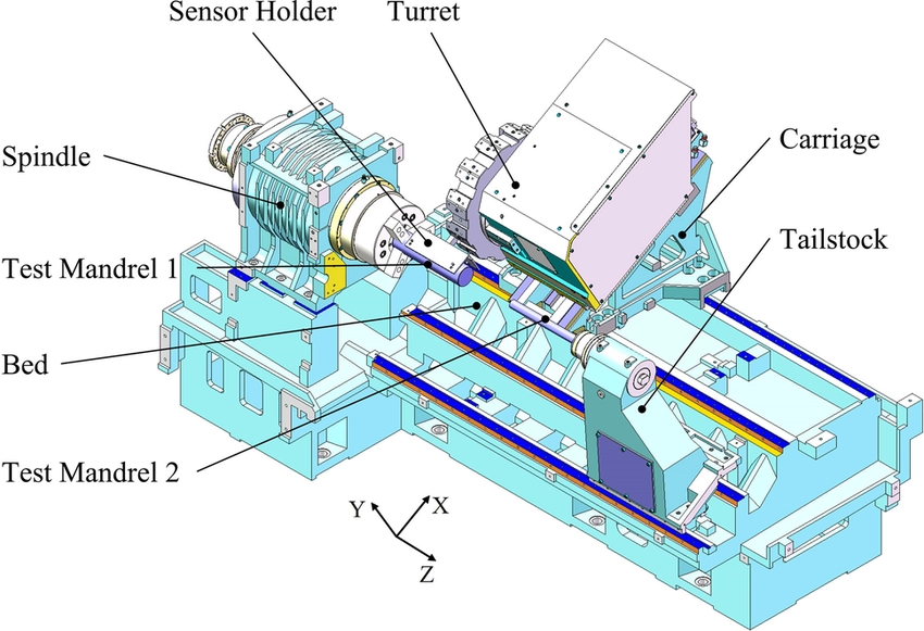
In turning, the raw material (typically a round bar) is held in a chuck and spun at high RPM. A single-point cutting tool moves linearly along the X and Z axes to “peel” away material, much like peeling an apple.
A technical diagram showing the CNC turning process where the chuck rotates the workpiece while the tool remains stationary.
Unlike milling, turning uses single-point cutting inserts. This results in continuous cutting, where the tool stays in constant contact with the material. This continuous engagement typically produces superior surface finishes on cylindrical features.
Key Turning Sub-Processes
OD Turning: Removing material from the outer diameter to reduce size.
Boring (ID Turning): Enlarging a pre-drilled hole to precise dimensions.
Facing: Cutting the end of the bar flat to establish a length reference.
Threading: Cutting external or internal screw threads (often faster and stronger than milling threads).
CNC Milling vs CNC Turning: 7 Critical Differences
To make an informed manufacturing decision when comparing CNC milling vs CNC turning, we must analyze these processes across seven technical dimensions.
1. Geometries & Part Shapes
Milling: Best for non-symmetrical, square, or block-like parts. It excels at creating complex 3D contours, pockets, and holes that are not on the center axis.
Turning: Strictly for cylindrical or axially symmetrical parts (shafts, rings, discs, pins).
2. Surface Finish Quality (Ra)
Turning Wins: Because the cutting is continuous, turning typically produces a smoother, more uniform surface finish (Ra 0.4 – 1.6μm is standard) without the “scallop marks” often left by milling tools.
Milling: Often requires secondary “finish passes” with slow feed rates to match the surface quality of a lathe.
3. Cutting Mechanism & Heat
Milling (Interrupted Cut): The tool teeth enter and exit the cut. This cyclic thermal stress causes mechanical shock.
Turning (Continuous Cut): The tool is under constant thermal and mechanical load. Heat management is critical, usually requiring high-pressure coolant to evacuate heat and chips.
4. Tooling Cost
Turning is Cheaper: Lathe inserts are relatively inexpensive and have multiple cutting edges per insert.
Milling is Higher: Solid carbide end mills are expensive and can wear out faster due to the shock of interrupted cutting.
5. Material Removal Rate (MRR)
Turning: Generally has a higher MRR for reducing round stock. It is the fastest way to turn a 50mm bar into a 20mm shaft.
Milling: Slower for removing large amounts of material from the outside of a cylinder.
6. Workholding (Clamping)
Milling: Uses vises, fixtures, or toe clamps. Setup can be time-consuming for odd shapes.
Turning: Uses a chuck (3-jaw or collet). Setup is extremely fast and self-centering for round stock.
7. Cost Implications
The choice of machine drastically affects the final price per part.
Part Type
Milling Cost
Turning Cost
Round Shaft
High (Requires Rotary Table + Slow)
Low (Fast + Efficient)
Square Block
Low (Standard Vise Setup)
Impossible (without special fixtures)
Hex Bolt
Medium (Multiple Setups)
Low (Turned + Live Tooling)
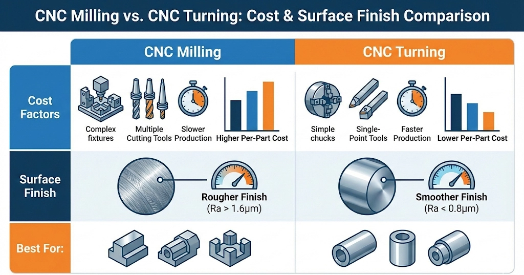
A comparison chart highlighting the cost and surface finish differences between CNC milling and CNC turning processes.
The Hybrid Era: Turn-Mill Centers
Modern manufacturing is blurring the lines between these two processes. Turn-Mill Centers (often called Swiss Lathes or Multitasking Machines) combine a traditional lathe with “Live Tooling.”
Live tooling consists of small milling spindles mounted in the lathe turret. This means the machine can turn a shaft, stop the spindle, and then use a milling tool to drill a cross-hole or mill a flat surface—all in one setup.
Capability: Complex parts completed in “Done-in-One” operations.
Benefit: Eliminates the need to manually move a part from a lathe to a mill, cutting lead times by up to 50% and improving accuracy.
Close-up view of a CNC Turn-Mill center equipped with live tooling for multitasking machining operations.
Conclusion: Which Process Should You Specify?
The rule of thumb for DFM in CNC milling vs CNC turning is simple:
If the part can be made on a lathe (it is round/symmetrical), make it on a lathe. It is almost always faster, cheaper, and produces a better finish.
If the part is not round, or has complex features that cannot be spun, Milling is your choice.
At JFManufacturer, we don’t force your part into the wrong process. We utilize both high-speed 5-axis Milling Centers and Precision Turning Centers to ensure you get the best quality at the lowest cost.
Ready to start your project?
Upload your CAD file today. Our automated DFM system will analyze your geometry and route your part to the most efficient machine for the job.
Frequently Asked Questions about Milling vs. Turning
Q1:What is the main difference between CNC milling and CNC turning?
The fundamental difference lies in the movement of the workpiece and the tool. In CNC milling, the workpiece is stationary while the cutting tool rotates to remove material. In CNC turning, the workpiece rotates at high speed while a stationary cutting tool moves against it. Milling is ideal for square or complex shapes, while turning is best for cylindrical parts.
Q2:Which process is cheaper: CNC milling or CNC turning?
For cylindrical parts (like shafts or pins), CNC turning is generally cheaper and faster than milling because it removes material more efficiently. However, for non-cylindrical or block-shaped parts, CNC milling is the standard and most cost-effective choice. Complex parts requiring both processes often benefit from Turn-Mill centers to reduce setup costs.
Q3:Does turning produce a better surface finish than milling?
Generally, yes. CNC turning uses continuous cutting, where the tool stays in constant contact with the material, typically resulting in a smoother, more uniform finish (Ra 0.4–1.6μm). CNC milling involves interrupted cutting (tool teeth entering and exiting), which can leave small scallop marks, often requiring a secondary finish pass to achieve comparable smoothness.
Q4:Can a CNC mill create round parts?
Yes, a CNC mill can create round features or cylindrical parts using interpolation (moving the X and Y axes simultaneously). However, this is typically much slower and less accurate than using a lathe. It is usually only done if the round feature is part of a larger, non-cylindrical component that cannot be turned.
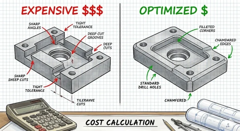
Why does a simple bracket cost $150? The answer is usually hidden in a 90° internal corner or an unnecessary ±0.01mm tolerance. This engineer’s handbook breaks down the mathematics of...
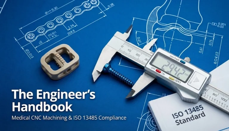
In the general manufacturing sector, a “quality part” is one that meets the print specifications. In the medical device industry, meeting the print is merely the starting line. A truly...
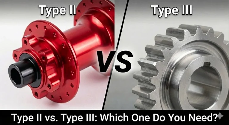
Specifying "Anodize" isn't enough. There is a massive engineering gap between Type II (Decorative) and Type III (Hardcoat). This guide breaks down the MIL-A-8625 standards, the "50/50 Rule" of dimensional...
In the world of precision manufacturing, “exact” is a theoretical concept, not a reality. No machine—no matter how advanced—can produce a part that is perfectly 100.000 mm long every single...
Master sheet metal design with our 6 fundamental tips. Learn about uniform wall thickness, bend radii, and hole positioning for cost-effective fabrication....
Ready to get started? Upload your CAD files and project details here. Our engineering team will review your request and provide a detailed quote, typically within 24 hours.